
Abstract: CNC lathe, also known as CNC lathe, namely computer numerical control lathe, is the most widely used CNC machine tool in China, accounting for 25% of the total number of CNC machine tools. CNC lathes are mainly used to process shafts and rotary parts. They can automatically complete the cutting of internal and external cylindrical surfaces, circular arc surfaces, end faces, threads and other processes. They are suitable for machining shafts or discs with complex shapes and high accuracy requirements. Taking the spindle motor of a CNC lathe controlled by a frequency converter as an example, this paper describes in detail the structure and technological characteristics of the CNC lathe, as well as the advantages of the application of the frequency converter on the CNC lathe.
Keywords: CNC lathe inverter closed-loop vector spindle positioning
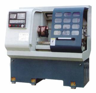
1. Introduction to CNC lathe CNC lathe is also called CNC (Computer numerical control) lathe, which is an automatic machine tool controlled by programs. CNC lathes are mainly used to process shafts and rotary parts. They can automatically complete the cutting of internal and external cylindrical surfaces, circular arc surfaces, end faces, threads and other processes. They are suitable for machining shafts or discs with complex shapes and high accuracy requirements. CNC lathe is mainly composed of mainframe, CNC device, driving device and auxiliary device. Mainframe, which is the main body of CNC lathe, includes machine body, column, spindle, feed mechanism and other mechanical parts. The numerical control device, which is the core of the numerical control lathe, includes hardware (printed circuit board, CRT display, key box, paper tape reader, etc.) and corresponding software, which is used to input digitized part programs, and complete the storage of input information, data transformation, interpolation and various control functions. The driving device is the driving component of the actuating mechanism of the numerical control lathe, including the spindle driving unit, the feed unit, the spindle motor, the feed motor, etc. Auxiliary devices refer to some necessary supporting parts of CNC lathe to ensure the operation of CNC lathe, such as cooling, chip removal, lubrication, lighting, monitoring, etc.
2. Field working condition 2.1 Spindle motor parameters
| Motor type | Variable frequency asynchronous motor | Rated power | 2.2KW | Rated speed | 1430r/min |
| Rated voltage | 380V | Rated current | 6.0A | Rated frequency | 50HZ |
| Control mode | Terminal control | Frequency setting mode | Analog quantity setting (0-10V) | control model | Closed loop vector control mode |
2.2 Realistic pictures


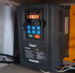
Figure (1) NC Lathe Figure (2) Application on NC Lathe
3. Process requirements and frequency converter configuration
The spindle motor of CNC lathe requires that the frequency converter be fast and stable when starting and stopping, and the motor has no squeal and obvious jitter. The torque response shall be fast and the speed stabilization accuracy shall be high; Strong anti-interference ability and convenient maintenance. The maximum speed of the motor is required to reach 3000 r/min, the on-site speed pulse encoder is installed on the lathe spindle, the lathe spindle and the spindle motor are connected by synchronous belt, and the ratio of belt input and output pulley diameter is 1:1. At the same time, the lathe spindle is required to achieve positioning control. When a workpiece is processed, the lathe spindle will return to the initial position. At this time, the processed workpiece will be removed and a workpiece to be processed will be reinstalled.
In view of the above process requirements, our company specially selects a high-performance closed-loop vector spindle positioning inverter with a power level of 4KW and a model of GD35-004G-4-A1.
4. Commissioning process and actual effect
4.1 Commissioning process and use effect
(1) Encoder parameter and direction setting
After connecting the CNC system, frequency converter and speed pulse encoder, test the encoder. Set the encoder wire number P20.01, set P00.00=2, P00.10=20Hz, and run the motor. At this time, the motor rotates to 20Hz. Observe that the speed measurement value of P18.00 should be close to 20Hz. If the speed measurement value is negative, it indicates that the encoder direction is reversed. Just set P20.02=1. If the speed measurement value deviation is large, it indicates that P20.01 is set incorrectly. Observe whether P18.02 Z pulse count value fluctuates. If it fluctuates, it indicates that the encoder has interference or P20.01 is set incorrectly. Check whether the wiring and shield wire are well grounded.
(2) Self learning of motor parameters
Record the motor nameplate parameters, and then set the parameters P02.00~P02.05. Set P00.00=1, open loop vector operation mode, and set parameter P00.15=1 (rotation parameter self-learning). At the same time, give the operation command, the motor will stop first and then rotate to 2/3 of the rated speed. After self-learning, the motor will automatically stop, and the keyboard will display - END -, and the learned parameters will be saved in P2 group of motor parameters P02.06~P02.10.
Note: The motor shaft needs to be disconnected from the mechanical load for the above dynamic self-learning, while the mechanical load does not need to be disconnected for the static self-learning.
(3) Commissioning motor
Set P00.00=3, closed loop vector control mode, and set operation command channel and frequency setting source at the same time. Adjust the acceleration and deceleration time and PI parameters of P3 group speed loop and current loop to ensure smooth operation within the whole range.
(4) Terminal function setting
Refer to P5 and P6 group input and output terminal functions in the manual to set the terminal functions. Note: The instruction document consists of the Goodrive300 product manual and the additional manual.
When the lathe spindle is used to process the workpiece, the speed is required to be set as 850r/min, and the closed-loop vector control mode is adopted, so the speed fluctuation is small and the speed stability accuracy is high. The motor shall be free of abnormal noise and obvious jitter. When a workpiece is processed, switch to the positioning mode, and the spindle can return to the initial position accurately. The application of special frequency converter for spindle positioning on CNC lathe can fully meet customer needs.
4.2 Typical parameter setting of frequency converter
| Serial No | Function code | Name | Set value | Explain |
| 1 | P00.00 | Speed control mode | 3 | Closed loop vector mode |
| 2 | P00.01 | Run command channel | 1 | Terminal operation channel |
| 3 | P00.03 | Maximum output frequency | 100HZ | |
| 4 | P00.04 | Upper limit of operating frequency | 100HZ | |
| 5 | P00.06 | A Frequency command selection | 1 | Analog quantity AI1 |
| 6 | P00.11 | Acceleration time 1 | 1S | |
| 7 | P00.12 | Deceleration time 1 | 2S | |
| 8 | P01.13 | Deadband time from positive to negative | 1S | |
| 9 | P05.01 | S1 terminal function selection | 1 | Forward running |
| 10 | P05.02 | S2 terminal function selection | 2 | Reverse operation |
| 11 | P05.03 | S3 terminal function selection | 45 | Spindle return to zero |
| 12 | P06.04 | Relay RO2 output selection | 5 | Inverter fault |
| 13 | P22.00 | Spindle positioning mode selection | 41 | Spindle positioning enable; Pulse valid |
| 14 | P22.01 | Spindle quasi stop speed | 5HZ | |
| 15 | P20.02 | Encoder direction | 0 or 1 | Adjust encoder direction |
| 16 | P22.03 | Spindle zero position | 0~4096 | Adjust zero position |
5. Conclusion
Previously, the spindle positioning function of CNC lathe was completed by the servo driver. After the special frequency converter for spindle positioning is used to replace the servo driver, it has excellent performance and the same effect as the servo driver for spindle positioning control, and can greatly reduce the cost of CNC lathe.
Sweep it
Linecome