
Abstract: NC gun drill is an efficient, high-precision and highly specialized deep hole processing machine tool, which is widely used in deep hole processing of parts in automobile, motorcycle industry, mold industry, military industry, aerospace and other industries. This paper takes a numerical control gun drill spindle motor produced by a machine tool 0EM accessory manufacturer as an example, and describes the process characteristics of the numerical control gun drill in detail, as well as the advantages of the inverter in the application of the numerical control gun drill spindle motor.
Keywords: NC gun drill, inverter, closed-loop vector deep hole machining

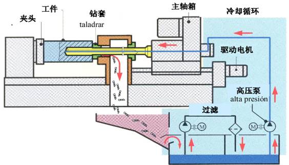
Schematic Diagram of NC Gun Drill Deep Hole Processing
1. Introduction to CNC gun drill and its process characteristics
In machine parts processing, when the depth diameter ratio L/D is greater than 5, it is generally called a deep hole. Deep hole processing with a depth diameter ratio of about 40-50 is a kind of hole processing technology with high processing difficulty, high technical content and high processing expertise. The traditional fried dough twist drill in deep hole processing, there will be difficult chip removal and derived from the short life of the drill and other adverse factors. Compared with the traditional fried dough twist drill, the NC gun drill has the following advantages in deep hole processing:
(1) The chip removal is smooth. When NC gun drill is used to process deep holes, cutting fluid with a certain pressure can well separate, roll and break chips in the hole through the barrel and cutter head, and at the same time forcibly discharge the chips.
(2) Adequate cooling and lubrication. In the process of drilling cuttings, the cutting fluid with certain pressure can not only take away the heat generated at high speed, but also play a role in lubrication and anti-corrosion.
(3) Good machining accuracy and surface roughness.
(4) High processing efficiency and low labor intensity. Because the cutting speed and feed rate of the NC gun drill are faster than those of the ordinary cutting, the iron chips are forced out by the cutting fluid, and there is no chip dumping in the process, so the processing efficiency is high. The CNC gun drill is a semi-automatic machine tool, which greatly reduces the labor intensity of workers.
2. Site conditions
2.1 Motor parameters
Motor type | Three phase asynchronous motor | Rated power | 3.7KW | Rated speed | 1500r/min |
Rated voltage | 380V | Rated current | 9.5A | Rated frequency | 50HZ |
control mode | Terminal control | Frequency setting mode | Frequency setting mode | Control model | Closed loop vector control mode |
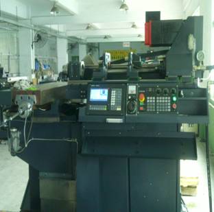
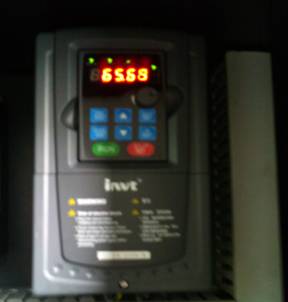
2.2 Realistic pictures


CNC gun drill machine Frequency converter applied to spindle motor
3. Requirements of NC gun drill spindle motor on frequency converter
NC gun drill spindle motor requires frequency converter to realize stepless speed regulation. NC gun drill spindle motor requires that the frequency converter has large starting torque at low frequency and can start and stop quickly. The torque response shall be fast, the speed stability accuracy shall be high, and the anti-interference ability shall be strong. At high speed, the motor has low noise and no abnormal jitter. The maximum speed of spindle motor is 6300r/min, and the maximum output frequency is 210HZ. The speed pulse encoder is installed on the spindle motor. The gun drill spindle and the spindle motor are connected through a synchronous belt. The input/output pulley diameter ratio is 1.5:1, that is, the maximum speed of the spindle motor is 6300r/min, and the maximum speed of the gun drill spindle is 4200r/min.
4. Advantages of application in CNC gun drill
(1) Using high-performance closed-loop vector control mode, the inverter has excellent control performance, no matter in acceleration and deceleration time, torque, torque dynamic response speed, operating current, motor noise, speed stability accuracy, etc.
(2) Strong overload capacity, excellent current limiting characteristics, suitable for heavy load applications, can effectively reduce inverter overload, over-current protection maloperation, and maximize production continuity.
(3) With strong environmental adaptability, the structure adopts independent air duct design, which can be used in harsh environments such as oil pollution, high dust, high humidity and heat. It can effectively reduce the frequency converter failure rate and extend the service life.
(4) C3 filter is equipped as standard to effectively filter the interference of the power grid to the frequency converter, and at the same time, suppress the interference of the high-order harmonic generated by the rectifier switch components of the frequency converter to the weak current signal of the control circuit, so as to ensure the stability and reliability of the system.
5. Commissioning process and parameter setting
5.1 Commissioning steps
(1) Encoder parameter and direction setting
After connecting the CNC system, frequency converter and speed pulse encoder, test the encoder. Set the encoder wire number P20.01, set P00.00=2, P00.10=20Hz, and run the motor. At this time, the motor rotates to 20Hz. Observe that the speed measurement value of P18.00 should be close to 20Hz. If the speed measurement value is negative, it indicates that the encoder direction is reversed. Just set P20.02=1. If the speed measurement value deviation is large, it indicates that P20.01 is set incorrectly. Observe whether P18.02 Z pulse count value fluctuates. If it fluctuates, it indicates that the encoder has interference or P20.01 is set incorrectly. Check whether the wiring and shield wire are well grounded.
(2) Self learning of motor parameters
Record the motor nameplate parameters, and then set the parameters P02.00~P02.05. Set P00.00=1, open loop vector operation mode, and set parameter P00.15=1 (rotation parameter self-learning). At the same time, give the operation command, the motor will stop first and then rotate to 2/3 of the rated speed. After self-learning, the motor will automatically stop, and the keyboard will display - END -, and the learned parameters will be saved in P2 group of motor parameters P02.06~P02.10.
Note: The motor shaft needs to be disconnected from the mechanical load for the above dynamic self-learning, while the mechanical load does not need to be disconnected for the static self-learning.
(3) Commissioning motor
Set P00.00=3, closed loop vector control mode, and set operation command channel and frequency setting source at the same time. Adjust the acceleration and deceleration time and PI parameters of P3 group speed loop and current loop to ensure smooth operation within the whole range.
(4) Terminal function setting
Refer to P5 and P6 group input and output terminal functions in the manual to set the terminal functions. Note: The instruction document consists of the Goodrive300 product manual and the additional manual.
5.2 Typical parameter setting
| Function code | Name | Setting value | Remarks |
| P0.00 | Speed control mode | 3 | During debugging, first set 2 (V/F control), and then set it to 3 after confirming that the encoder is correct. See the following debugging steps for details |
| P00.01 | Run command channel | 1 | Terminal operation |
| P00.03 | Maximum output frequency | 210HZ | 1. 210Hz corresponds to 6300rpm (4-pole motor) |
| 2. When setting the frequency of analog quantity, 10V corresponds to the maximum output frequency, which can be adjusted as required | |||
| P00.04 | Upper limit of operating frequency | 210HZ | |
| P00.06 | A Frequency command selection | 1 | Analog quantity AI1 setting |
| P00.11 | Acceleration time 1 | 3S | |
| P00.12 | Deceleration time 1 | 3S | |
| P03.03 | Speed loop proportional gain 2 | 15 | The proportional gain of speed loop and current loop can be factory value. If the motor vibrates, the gain can be reduced appropriately |
| P03.09 | Current loop proportional gain | 800 | |
| P03.22 | Weak magnetic coefficient | 0.6 | Field weakening control parameters do not need to be adjusted generally |
| P03.26 | Field weakening proportional gain | 800 | |
| P05.01 | S1 terminal function | 1 | Forward running |
| P06.04 | Relay RO2 output selection | 5 | Inverter fault |
| P06.15 | AO2 output selection | 9 | Output torque |
| P08.37 | Energy consumption brake enabling | 1 | |
| P20.01 | Number of encoder pulses | 1024 | Set according to the actual number of lines of the encoder |
| P20.02 | Encoder direction | 0 or 1 | The encoder direction can be determined according to the positive and negative values of P18.00 speed measurement |
| P18.00 | Encoder measured frequency | 1. This parameter is read-only and cannot be changed | |
| 2. The encoder speed measurement value should be consistent with the actual speed and positive and negative directions, otherwise the encoder direction is reverse or the encoder pulse number is set incorrectly | |||
| P18.02 | Encoder Z pulse count value | 1. This parameter is read-only and cannot be changed | |
| 2. The value of Z pulse count should remain unchanged, otherwise it indicates that there is interference or the encoder line number is set incorrectly |
6. Customer evaluation
In the process of machine test, compare with a brand of servo driver: when the CNC gun drill is used for deep hole processing, the spindle speed is generally required to be between 2100 r/min and 2500 r/min, and the actual test result is that the performance of the inverter in terms of motor noise and vibration is better than that of a brand of servo driver. The application of frequency converter on the spindle motor of numerical control gun drill can fully meet customer requirements and obtain high recognition from customers.
Sweep it
Linecome